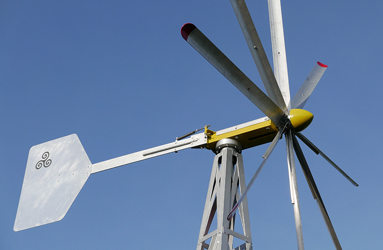
 The Mk2 Design rendered in SOLIDWORKS
But it has been a long story to get here...
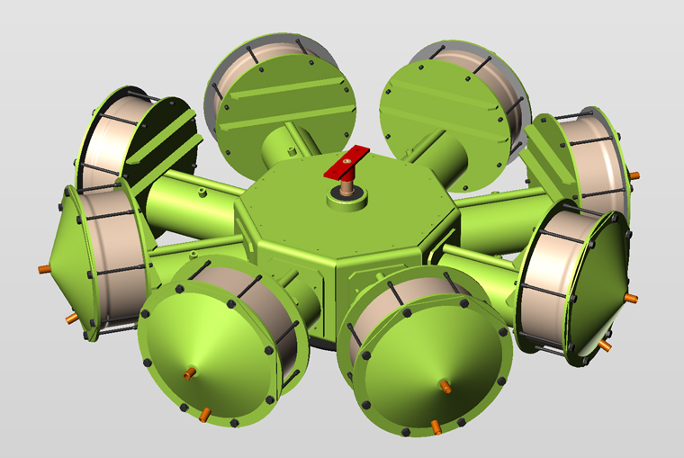
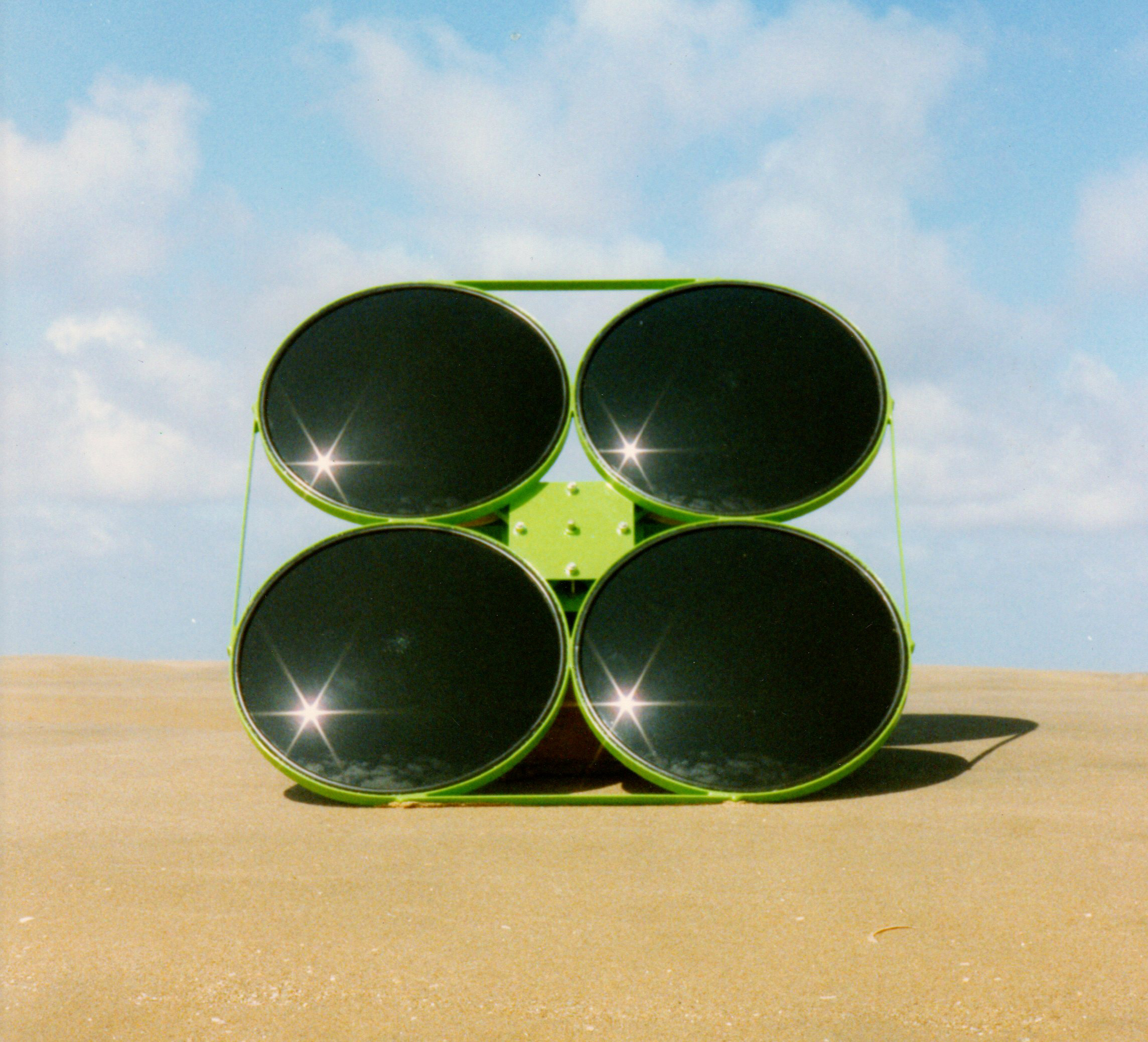 Photo from a related earlier project
My interest in Air Engines began back in 1988 after returning home from working in Iran as an agricultural machinery project engineer. I wanted to explore options for a 'solar powered water pump' other than photovoltaic cells, which lead me to this engine. This personal project continued parallel to my employment back then, until a novel four cylinder alpha type diaphragm engine arrangement was created with a central "Z" crank. Two British patents (now expired) were later obtained, and in 1999 a 'Smart Award' grant was giving by the British Government's department of Trade and Industry for its continued development. However, diaphragms under pressure and elevated temperature are fraught with problems, including stiffness, and by 2002 that original project had to be adjourned.
The central "Z" crank diaphragm engine CAD design
with black diaphragms, and yellow 'L' shaped Regenerator

However, a great deal of valuable practical experience from that was brought forward into the current project.
Development Ethos
Because the Hot Air engine is inherently more efficient than a Diesel engine, nearly all development projects in the 20th century were aimed at making it more compact, so that the power density could be competitive. Unfortunately by making the engine compact with high pressure air or gas, and running at fast revolutions brought many problems, and lost its efficiency advantage. So it remained peripheral.The current project has a very different ethos, it is bulky and slow speed and happy with it, as long as it is not bigger than other farm machinery it is fine! Also this is a green energy heat pump, not a fossil fuel engine. Rather the aim of this design is to get affordable reliability with long life in rural applications.
The basic design needs to be capable of being manufactured in relatively small scale industry. Whereas high volume production could be optimized by certain design and material changes.
Development of the Experimental Model
It was found that there are special requirements with this application as the speed varies from zero up, so piston/gland sealing has to be particularly good at slow speed. There are also lubrication issues with a slow vertical crank engine, but lubrication itself can be used to enhance the sealing!Non-metallic materials are chosen for displacer and displacer tube to reduce heat conduction losses, and trials have been performed with heat resisting resin fibreglass composites, foam-glass insulation, Acetal plastic and balsa wood. Graphite dry-lub bearings have been assessed for use in sealing glands.
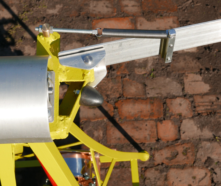
Storm Force
Hot Air machines have an unusually large range of possible variations, and all are interconnected in the performance achievable, but there is no substitute for a physical test rig to try out options. Doing this as a model is just a cost effective way of getting the design viable.
Mk2 DESIGN
Thermodynamic calculations and experience from the experimental models showed that some changes were needed. It was always intended that it would have a fully enclosed crankcase with multi-cylinders in radial formation to even out the torque requirement, but there are also some other developments: These include the compression pistons now having a longer stroke to give a higher compression ratio, while the displacer retains its large diameter with very short stroke. Non-metallic materials are used to reduce heat conduction losses at key places. The wind turbine itself is increased to eight blades, as a balance between torque and efficiency.
Calculated Pressure-Volume curve used in the Mk2 design
Wind power is proportional to the cube of the wind-speed, which the torque requirements of ordinary refrigerant heat pumps cannot accommodate. – This heat pump is different! This design has variable pressurizing, such that as the wind speed increases, so does the cyclic pressure until the heat output reaches its design maximum of 4.5kW with a COP of 3.0. While for a gentle breeze, the machine will be unpressured but still turning, giving a smaller heat output though keeping the system warm. For stronger winds, the eight bladed turbine becomes inefficient – though this was not usable power, and it makes the turbine output match the heat pump power curve. For storm-force winds there is the protection device shown above.
When an idea is theoretically possible such as this, development engineering is only a matter of getting it right, because it is do-able!

Design Rationale
Stirling Engines are technically very alluring – they are the perfect engine in terms of having the theoretical maximum possible efficiency (same as Carnot Efficiency) and simplicity without valves or noise in a practical engine. But they are limited by heat transfer – Getting enough where needed, and holding it back where unwanted. This, plus the need to match the wind turbine output, has driven the Design.
| Mk 2 Design Specifications | |
| Number of Cylinders | 8 |
| Compression Ratio | 2.5 : 1 |
| Piston Diameter | 5" (127mm) |
| Piston Stroke | 150mm |
| Displacer Diameter | 12" (305mm) |
| Displacer Stroke | 10mm |
| Max Charge Pressure | 29 psi Gauge |
| Max Working Pressure | 137 psi Gauge |
| Design Max Heat Output | 4500 Watts |
| Design Running Speed | 157 RPM |
| Design Max Over-speeding | 500 RPM |
| Design Temp Differential | 60 degrees C |
| Design C.O.P. | 3.0 |
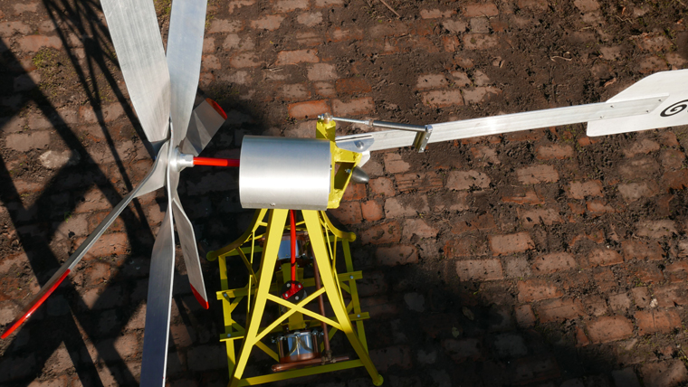
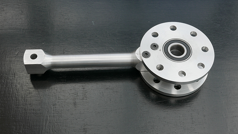
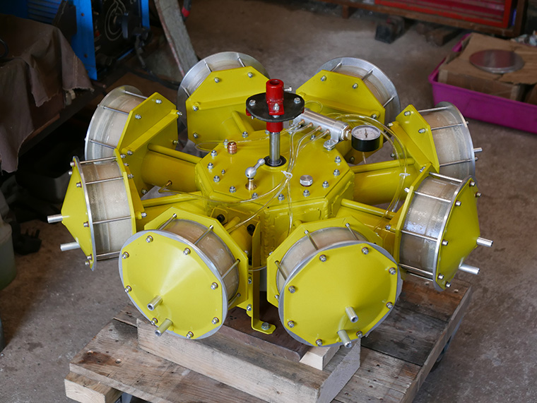
Mk2 Prototype Construction Photos
Continuing development of the design, a half scale prototype was built in the same home workshop as the models. It also shows that full size machines could be produced in a relatively small factory.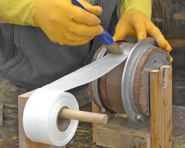
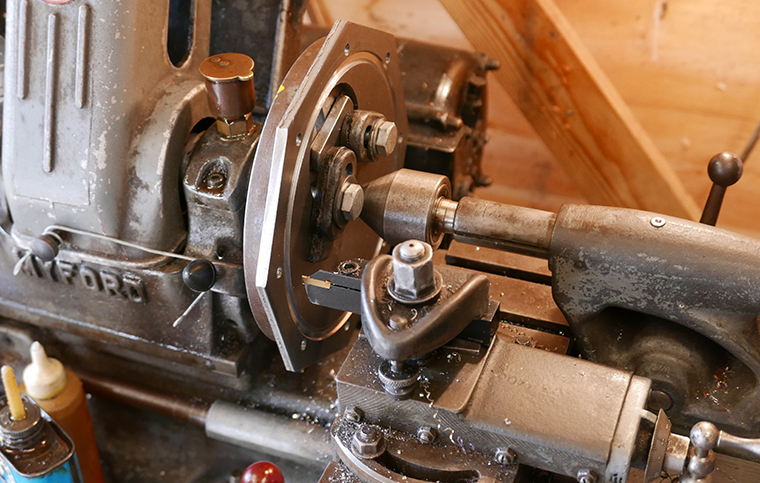
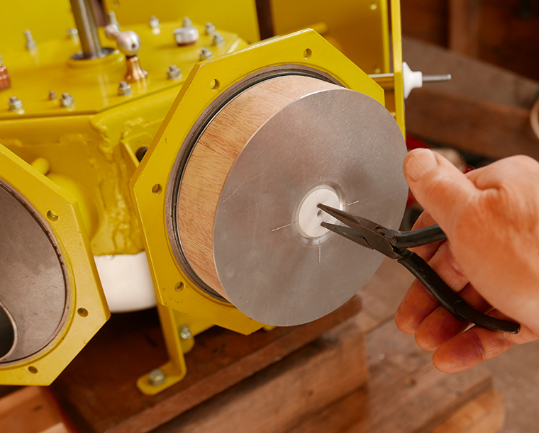
this is a four-stone adjustable hone.
The cold drawn seamless tubes were attached using silver solder.
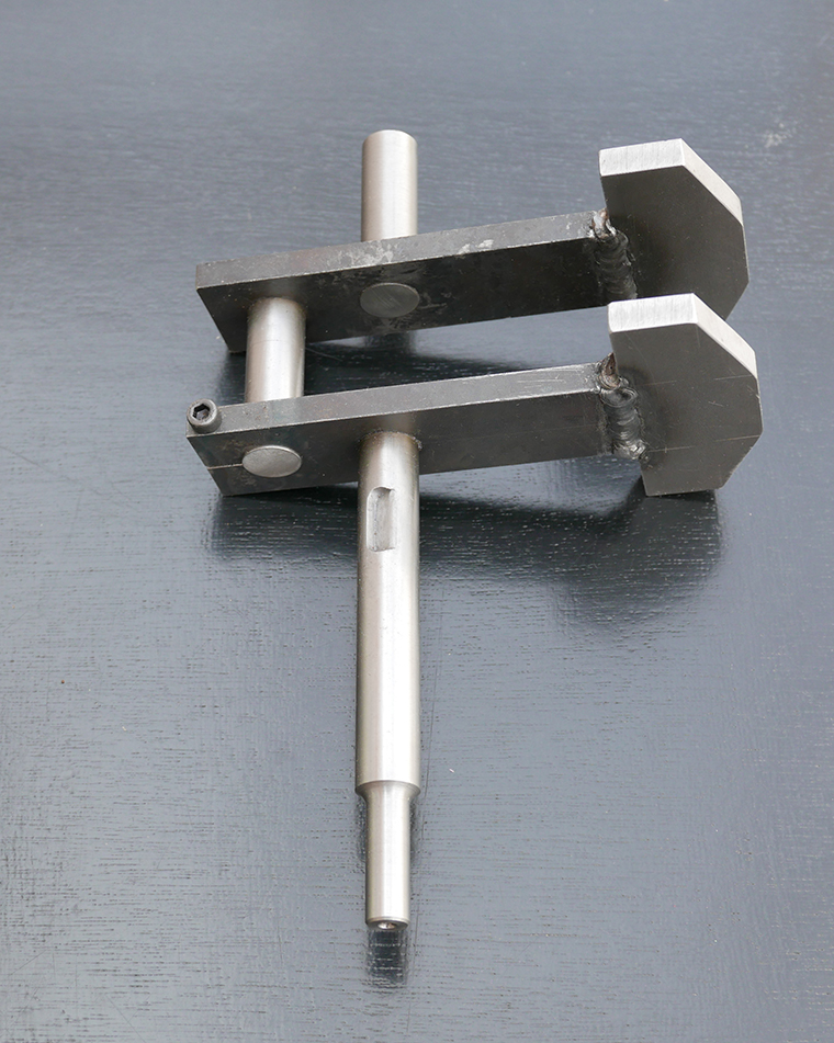
Fitting Balsa Displacer sandwich to dispacer rod
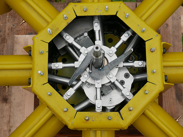
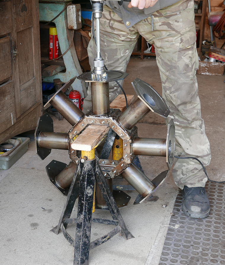
Inside crankcase with displacer drive pawls at top
slip eccentric switches from heater to cooler
This was intended as a half-scale prototype, but development now points towards keeping the smaller size, and running it faster. A simplified horizontal crank version with fewer cylinders is also planned.
using some of the same parts as the radial